User Guide
Creating a 3D View
To create a 3D view:
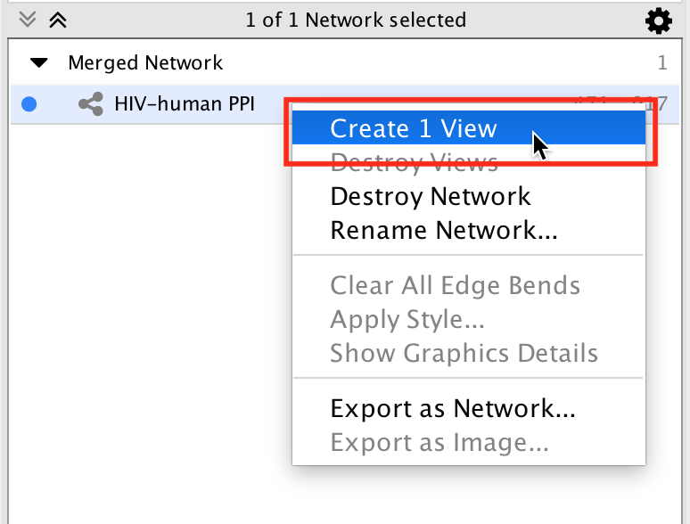
- Select a network in the Network panel.
- Right click on the network and select Create View (you may need to select Destroy View first).
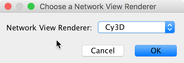
- In the “Choose a network view renderer” pop-up select Cy3D.
To create a 3D view without destroying the existing view:
- Open the network view in the standard 2D renderer.
- Select all the nodes (Select > Nodes > Select All Nodes).
- Click the New network from selection toolbar button.
- Close the network view that was just created.
- Select the newly created network in the Network panel.
- Right click on the network and select Create View.
- In the “Choose a network view renderer” pop-up select Cy3D.
Controlling the Camera
- Cy3D has 2 modes: camera mode and select mode.
- The modes are toggled using the toolbar in the 3D renderer view.
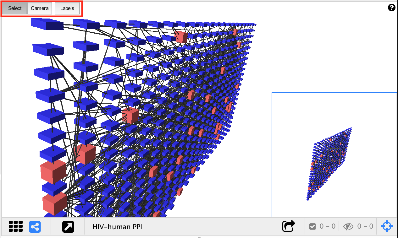
- In camera mode the mouse rotates the camera around the network. Mouse wheel moves the camera in and out.
- In select mode the mouse is used to select nodes and edges, and to activate the context menu.
- For a detailed list of controls click the (?) icon at the top right of the 3D renderer view.
3D Renderer Controls
| Toolbar | Buttons toggle between Select Mode and Camera Mode |
| Shift | Hold to force Select Mode |
| Alt | Hold to force Camera Mode |
Select Mode
| Left Click | Select Node or Edge |
| Left Click and Drag | Selection box |
| Ctrl + Left Click | Add to current selection |
| Right Click | Context menu |
Camera Mode
| Click and Drag (Near Center) | Orbit Camera |
| Click and Drag (Around Perimeter) | Roll Camera |
| Mouse Wheel | Zoom In/Out |
Keyboard Controls
| Up, Down, Left, Right | Orbit camera (at constant speed) |
| R | Reset camera to default position |
Layouts
Currently the only way to move nodes around in 3D is to apply a layout.
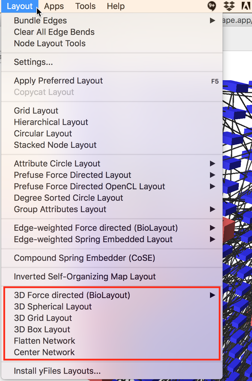
There are 4 3D layout algorithms available in the Layout menu:
- 3D Force Directed (BioLayout)
- 3D Spherical
- 3D Grid
- 3D Box
Additionally there are two other ways to manipulate the graph which are implemented as layouts:
- Flatten Network
- Sets the Z coordinate of every node to zero. It is useful if you would like to apply a 2D layout, because most of the existing 2D layouts just ignore the Z coordinate. Apply the Flatten layout before or after applying a 2D layout to fix the results of the 2D layout.
- Center Network
- Computes the centroid of all the nodes and translates the graph so that the centroid is the new origin.