User Guide
Creating a 3D View
To create a 3D view:
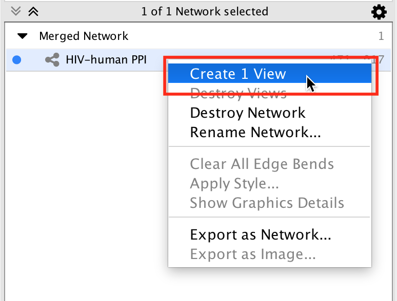
- Select a network in the Network panel.
- Right click on the network and select Create View (you may need to select Destroy View first).
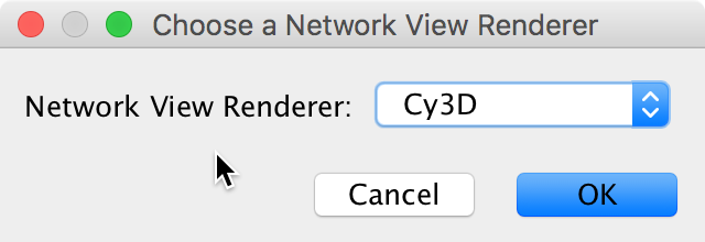
- In the “Choose a network view renderer” pop-up select Cy3D.
To create a 3D view without destroying the existing view:
- Open the network view in the standard 2D renderer.
- Select all the nodes (Select > Nodes > Select All Nodes).
- Click the New network from selection toolbar button.
- Close the network view that was just created.
- Select the newly created network in the Network panel.
- Right click on the network and select Create View.
- In the “Choose a network view renderer” pop-up select Cy3D.
Controlling the Camera
- Cy3D has 2 modes: camera mode and select mode.
- The modes are toggled using the toolbar in the 3D renderer view.
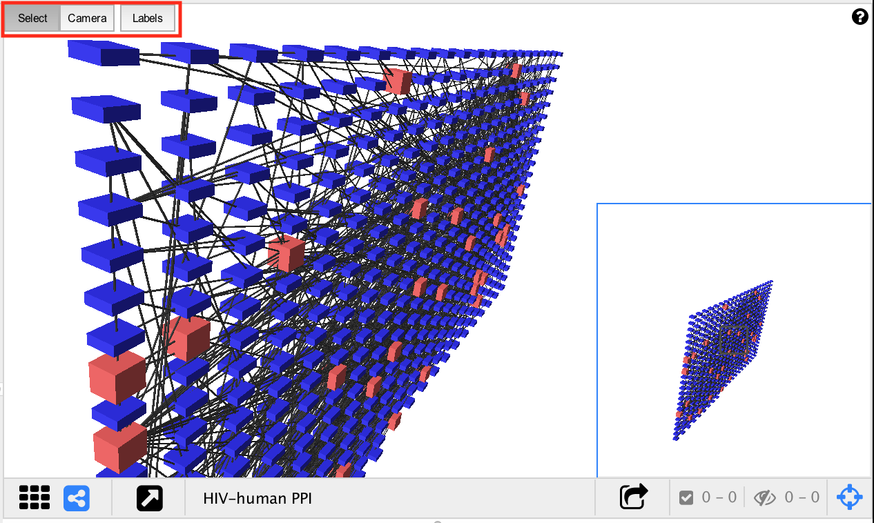
- In camera mode the mouse rotates the camera around the network. Mouse wheel moves the camera in and out.
- In select mode the mouse is used to select nodes and edges, and to activate the context menu.
- For a detailed list of controls click the (?) icon at the top right of the 3D renderer view.
3D Renderer Controls
| Toolbar | Buttons toggle between Select Mode and Camera Mode |
| Shift | Hold to force Select Mode |
| Alt | Hold to force Camera Mode |
Select Mode
| Left Click | Select Node or Edge |
| Left Click and Drag | Selection box |
| Ctrl + Left Click | Add to current selection |
| Right Click | Context menu |
Camera Mode
| Click and Drag (Near Center) | Orbit Camera |
| Click and Drag (Around Perimeter) | Roll Camera |
| Mouse Wheel | Zoom In/Out |
Keyboard Controls
| Up, Down, Left, Right | Orbit camera (at constant speed) |
| R | Reset camera to default position |
Layouts
Currently the only way to move nodes around in 3D is to apply a layout.
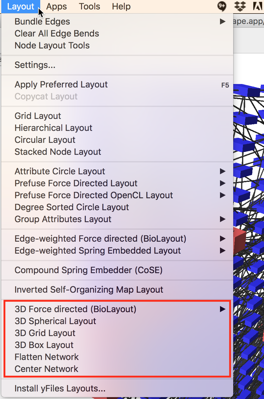
There are 4 3D layout algorithms available in the Layout menu:
- 3D Force Directed (BioLayout)
- 3D Spherical
- 3D Grid
- 3D Box
Additionally there are two other ways to manipulate the graph which are implemented as layouts:
- Flatten Network
- Sets the Z coordinate of every node to zero. It is useful if you would like to apply a 2D layout, because most of the existing 2D layouts just ignore the Z coordinate. Apply the Flatten layout before or after applying a 2D layout to fix the results of the 2D layout.
- Center Network
- Computes the centroid of all the nodes and translates the graph so that the centroid is the new origin.
Visual Properties
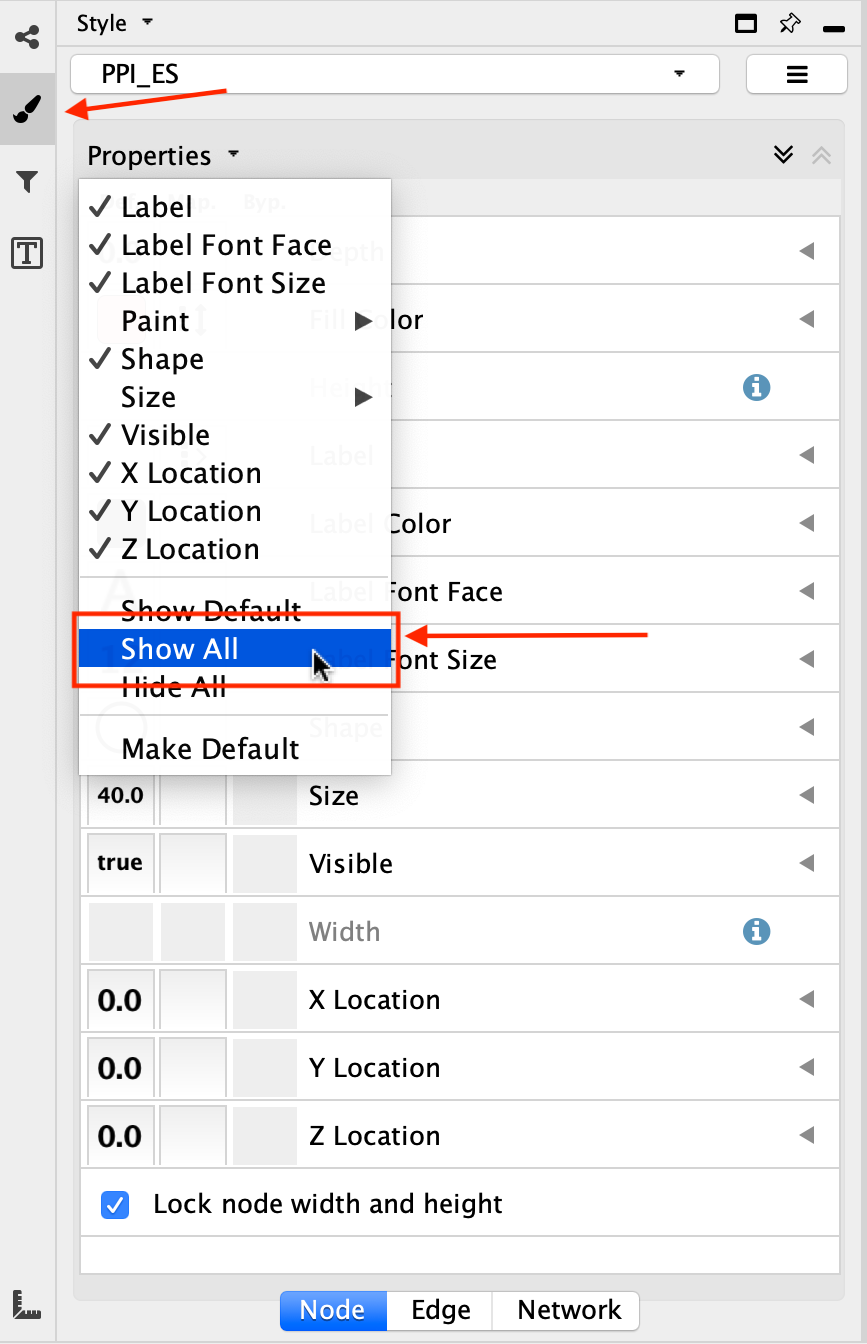
To view the complete list of visual styles that are supported by Cy3D…
- Go to the Style panel
- Click on the Properties drop down menu.
- Select Show All
- This can be done for each of the Node, Edge, and Network tabs.